Results and Design Guidance
This chapter collects what the models say about the 17HS19-2004S1 on the B-G431B-ESC1 at 24 V, and turns it into guidance for configuring the library and the board. All values come from the tests in the Test Catalogue; the assumptions behind them (datasheet motor parameters, detent and friction values, board passives) are listed in Motor Model and Power Stage Model.
Current loop
| Quantity | Value | Test |
|---|---|---|
| Bandwidth (design) | 1 kHz | — |
| Step 0 → 2 A: overshoot / rise (90 %) / settling (2 %) | 1.12 % / 0.35 ms / 0.40 ms | T04 |
| Same with R ×0.9 … 1.3, L ×0.8 … 1.2 | overshoot ≤ 5.2 %, settling ≤ 1.6 ms | T08 |
| Phase lag at 1 rev/s | about 4° | T03, T05 |
| Current ripple at 2 A, locked (20 kHz, 3 mH) | 23 mA p-p | T10 |
The pole-zero cancellation keeps the loop well damped for the whole tolerance range of
the datasheet; a hot winding (R +30 %) with a low inductance slows the last 2 % of the
step to 1.6 ms but does not destabilise it. Guidance: 1 kHz bandwidth at 20 kHz PWM
is a safe default; do not exceed fast_loop_hz / 4 (enforced by sstep_init()).
Voltage limit and speed
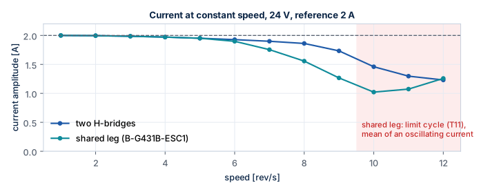
| Speed | Two H-bridges: current, scale, load angle | Shared leg (ESC1): current, scale, load angle |
|---|---|---|
| 2 rev/s | 2.00 A, 1.00, 6° | 2.00 A, 1.00, 6° |
| 4 rev/s | 1.97 A, 1.00, 12° | 1.97 A, 1.00, 12° |
| 6 rev/s | 1.93 A, 1.00, 18° | 1.90 A, 0.81, 19–20° |
| 8 rev/s | 1.86 A, 0.97, 24° | 1.56 A, 0.51, 36–39° |
| 9 rev/s | 1.73 A, 0.83, 31° | 1.27 A, 0.46, 48–50° |
| 10 rev/s | 1.46 A, 0.71, 42° | 1.02 A, 0.41, 51–63° (oscillating) |
| 12 rev/s | limit cycle, 16–95° | limit cycle, 3–134° |
(Unloaded rotor, 2 A reference, back-EMF feed-forward on; scale is the smallest factor the power stage applied to the requested voltage, 1 = not limited.)
With three legs the largest circular voltage is Vbus/√2: the ESC1 reaches the voltage
limit at about 6 rev/s at 24 V, two H-bridges at about 8 rev/s. Beyond the limit the
current — and the torque — drops with speed, and the load angle grows even without load.
Guidance: at 24 V on the ESC1 plan for at most 8 rev/s with useful torque
reserve; the torque available at speed n is roughly K_t · I(n), minus the angle
already used for acceleration. A higher bus voltage moves every speed in the table up
proportionally (the ESC1 accepts up to 6S LiPo voltages).
Rotor resonance
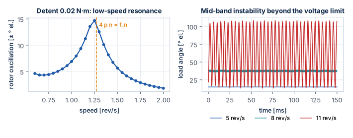
Low-speed resonance. The rotor on the current vector is a spring-mass system with
f_n = √(p K_t I / J) / 2π = 254 Hz at 2 A (248 Hz with the current loop). Any torque
ripple at that frequency excites it. The detent torque has four periods per electrical
period, so it excites the rotor at 4 p n = f_n, i.e. about 1.25 rev/s with the
rotor alone: with an assumed detent torque of 0.02 N·m the oscillation reaches ±14° there
against ±3–5° elsewhere. A load inertia lowers f_n (∝ 1/√J) and with it the resonant
speed.
Mid-band instability. As long as the current loop controls the current, it damps the rotor: no oscillation at 5 rev/s. Once the bridge limits the voltage, the drive behaves like a voltage source and the back-EMF coupling undamps the rotor: ±1.3° at 8 rev/s, a limit cycle of ±48° at 11 rev/s on the ESC1 (from about 12 rev/s with two H-bridges).
Guidance:
- Do not run continuously at the low-speed resonance; accelerate through it. Microstepping (M ≥ 16) already removes the full-step excitation; the detent torque remains.
- Keep the operating speed below the voltage limit (previous section) — that is also the region where the rotor is damped.
- Measure
f_non the real motor (a small angle step, as in T11a) and the detent torque; the resonant speed depends on both. - Active damping in the library (from the back-EMF estimate) is a possible extension.
Robustness
| Variation | Effect | Test |
|---|---|---|
| R ×0.9 … 1.3, L ×0.8 … 1.2 in the plant, nominal controller | current loop stable, settling ≤ 1.6 ms | T08 |
| 5× load inertia | synchronous at 4 rev/s, 50 rev/s², load angle 13° | T08 |
| 5× inertia + 0.15 N·m load + R ×1.3, L ×0.8 | synchronous, load angle 46° | T08 |
Load 0.25 N·m at 1 rev/s (below K_t I = 0.417 N·m) |
synchronous, load angle 37.2° = asin(T/(K_t I)) |
T06 |
Load 0.5 N·m (above K_t I) |
loss of synchronism after 152 ms | T06 |
Guidance: keep the static load below about 60 % of K_t I (0.25 N·m at 2 A) to leave
angle for acceleration; the load angle in the SIL diagram shows the reserve directly.
Power stage
| Quantity | Value | Consequence |
|---|---|---|
| Effective dead time (timer 500 ns) | 133 ns | phase voltage error ±0.135 V; distortion near the current zero crossing |
| Dead time margin | 154 ns | do not set the timer dead time below about 350 ns without measuring |
| Gate bump of the off switch | 3.7 V with 10 Ω (assumed) | check the real gate resistors / turn-off diodes |
| Shunt valid | 345 ns after the low-side command | sample centred; leg duty ≤ 0.956 |
| Current peak at 4 rev/s incl. ripple | 2.03 A | trip at 3.5 A leaves margin |
Open points
| Topic | Status | Where |
|---|---|---|
Measure R, L, K_t, detent torque, f_n of the real motor |
to do (P3) | Hardware Bring-up |
| Board passives (Rg, shunt, amplifier gain) from the schematic | to do | Power Stage Model |
| Dead time compensation in the library | planned; value and error table available | dead_time_ns, leg_error_table |
| Delay compensation (angle advance) | planned | Control Algorithms |
| Limit of the leg duty for valid shunt samples | planned | 0.956 from SP03 |
| ADC zero auto-calibration at enable | planned | — |
| Fast loop execution time on the STM32G431 | to measure (P3) | — |
| Scilab run of T08, T10–T12, X04, S01, S04 | pending | Test Catalogue |